
🔧 Suzuki DF250 Fault Code 34 Diagnostics: Don’t Blame the Sensor Too Soon
A Suzuki DF250 outboard losing power, switching to limp mode, or showing a warning light might look like a simple sensor failure. But when it comes to Suzuki DF250 fault code 34 diagnostics, 70% of the time the sensor isn’t the real issue.
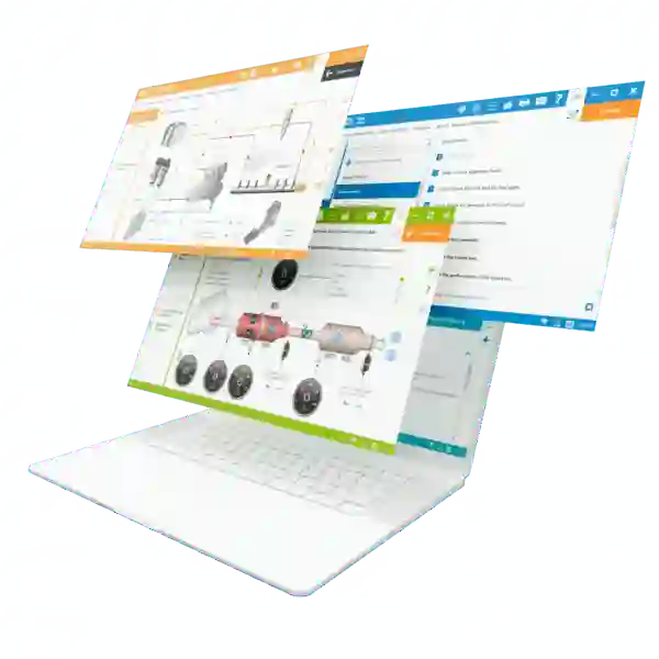
This article, powered by Jaltest INFO Web, walks you through how to properly diagnose, test, and fix fault code 34 without falling into the “sensor trap.”
This in-depth guide, based on Jaltest INFO Web, will teach you how to:
✅ Truly understand what Fault Code 34 means
✅ Properly test the CB5Q sensor
✅ Avoid unnecessary part replacements
✅ Solve the issue at its root — like a pro
🔍 What Exactly Is Fault Code 34?
- Label: Boost Air Pressure Sensor (Sensor 1)
- Function: Measures pressure inside the intake manifold
- Purpose: Enables real-time air/fuel ratio adjustment for optimal combustion
When this sensor fails:
- The ECU loses a critical reference
- Fuel injection becomes erratic
- The engine enters “safe mode” (reduced RPM, limited injection)
❌ The Common Mistake: Replacing the Sensor Too Quickly
In the workshop, 1 in 2 interventions end with the sensor being replaced… but the issue persists.
Why this approach is risky:
- The sensor might be working just fine
- The problem often lies in:
- Unstable ground
- Inconsistent power supply
- Interference from another component
- Corroded or damaged connector pins
- Unstable ground
The right method: interpret the code, then analyze the circuit under real conditions.
🛠️ Full Step-by-Step Diagnosis with Jaltest INFO Web
1. Establish Context
In Jaltest INFO Web:
- Enter Fault Code 34
- Access the repair guide
- Identify ECU configuration (2 or 3 connectors)
- Open the wiring diagram for the CB5Q sensor

2. Visual Inspection (Don’t Skip This)
- Open the engine cover
- Locate the boost pressure sensor (usually on the intake manifold)
- Disconnect the connector
Check for:
- Corrosion on terminals
- Loose or damaged pins
- Signs of moisture
💡 Pro tip: Take a picture of the connector before intervention for documentation.
3. Smart Electrical Testing (Multimeter + Jaltest)
| Pin | Test Type | Expected Value |
| Power (+) | DC voltage | +5V or +12V |
| Ground | Continuity (Ohm reading) | 0 to 0.2 Ω |
| Signal | Varying voltage (engine on) | 1 to 4.5V |
- Engine off: Confirm power and ground are present
- Engine running: Check for a variable signal that responds to throttle changes
🎯 Unstable power or ground? The problem is upstream — not the sensor itself.
4. Thoughtful Repair
Based on the findings:
- Clean the connector (use contact cleaner spray)
- Repair or replace any damaged wiring
- Replace the sensor only if:
- There’s no output signal
- Power and ground are confirmed good
- There’s no output signal
📍 Technical Insight: Why This Sensor Matters
The intake pressure sensor is critical for:
- Precise injection control
- Ignition timing strategy
- Triggering engine alerts
A bad signal can lead to:
- Excessive fuel consumption
- Torque loss
- Engine knock (pre-ignition)
- Overheating at high RPMs
💡 Some advanced technicians even use this sensor to detect intake leaks or abnormal boost pressure.
✅ Quick Pro Summary
| Step | Key Action |
| 1 | Identify and contextualize the code in Jaltest |
| 2 | Perform a detailed visual check of the sensor |
| 3 | Test power, ground, and signal with a multimeter |
| 4 | Repair or replace based on evidence, not guesswork |
🎯 Final Thought: A Sensor Doesn’t Lie — But It Can Be Misunderstood
With Jaltest INFO Web and a structured approach, Fault Code 34 becomes a starting point—not a guessing game.
Replacing a sensor isn’t a solution. Understanding it, testing it, and validating the fault is what separates a true technician from a parts changer.
👉 Request your free Jaltest INFO Web demo and learn how to improve your diagnostics today.