Are several ECUs showing faults at the same time, some systems no longer responding, and communication becoming unstable?
CAN Bus diagnostics is essential when several ECUs show faults, systems stop responding, or communication becomes unstable. Before assuming that several separate faults are occurring, it is worth checking the CAN Bus network.
Here are 7 essential measurements that can help guide the diagnosis quickly.
1. Measure Battery Voltage
Everything starts with the main power supply.
A weak battery or unstable voltage can affect several ECUs and generate communication errors.
Before going any further, check:
- battery voltage with the engine off;
- voltage during engine start;
- voltage with the engine running.
A poor power supply can sometimes explain several CAN Bus faults appearing at the same time.
2. Check CAN Network Resistance
With the ignition switched off, measuring resistance between CAN High and CAN Low provides an initial indication of network condition.
On many CAN networks using two 120 Ω terminating resistors, a value close to 60 Ω is normally expected.
A very different reading may indicate:
- a missing terminating resistor;
- a short circuit;
- a disconnected ECU;
- a wiring harness problem.
This simple measurement can save a significant amount of diagnostic time.
3. Check CAN High
When the network is operating, the voltage on the CAN High line changes while data is being transmitted.
A voltage that is fixed, too high or too low may indicate an electrical fault.
The objective is therefore not simply to record a value, but to check whether it changes normally while the network is communicating.
4. Check CAN Low
The same principle applies to CAN Low.
The two lines work together. A fault on just one of them may affect the entire network.
Comparing CAN High and CAN Low can help identify:
- a short circuit to ground;
- a short circuit to positive;
- an open circuit.
5. Check ECU Power Supplies
An ECU that no longer communicates is not necessarily faulty.
Before replacing it, check its power supply and ground connections.
A blown fuse, poor ground or damaged connector may simply prevent the module from joining the CAN network.
6. Test Wiring Continuity
Vibration, friction, moisture and previous repairs can damage CAN wiring.
Look for:
- broken wires;
- corroded connectors;
- pushed-back pins;
- crushed wiring;
- poor previous repairs.
Intermittent faults can be particularly difficult to identify. In these cases, monitor the measurements while gently moving the wiring harness.
7. Compare Results With the Network Diagram
A single measurement does not always provide the answer.
To understand what is happening, technicians need to know which ECUs are connected to the network, how they are connected and where the connection points are located.
This is where technical documentation becomes essential.
Jaltest INFO Web in Action
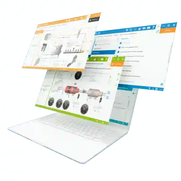
With Jaltest INFO Web, technicians can combine their electrical measurements with the technical information required for diagnosis.
Depending on the vehicle or machine, the platform can provide access to:
- wiring diagrams;
- ECUs present on the network;
- connectors and pinouts;
- component locations;
- fault code information;
- available reference values and inspection procedures.
Imagine that a transmission ECU is no longer communicating.
Instead of replacing the module immediately, the technician can follow its power supply on the wiring diagram, identify its CAN connections and check the circuit step by step.
A Simple Diagnostic Logic
For effective CAN Bus diagnostics, think:
Power supply → Resistance → CAN High → CAN Low → ECU → Wiring → Diagram
The goal is not to take more measurements. It is to measure in the right place and in the right order.
Conclusion
CAN Bus faults can make it appear that several systems have failed at the same time. In reality, one poor power supply, a damaged line or a faulty connector may be enough to disturb the entire network.
By combining simple electrical measurements with the technical information available in Jaltest INFO Web, technicians can reduce troubleshooting time and avoid unnecessary, costly component replacement.
On a CAN network, the right measurement in the right place can make all the difference.