On modern commercial vehicles, many sensors can trigger fault codes without being directly responsible for the issue. This is especially true for the NOx sensor, which is often wrongly blamed. With Jaltest, you can go beyond basic fault codes to assess the actual condition of the vehicle’s electronic communication network. Here’s a real-life case study involving a Renault Premium DXi, where accurate diagnostics prevented unnecessary replacement.
🔍 Intervention Context
Vehicle: Renault Premium DXi – Euro 5
Symptoms:
- Engine warning light on
- Active fault code related to the NOx sensor
- Limp mode activated (loss of engine power)
Objective: Determine the actual cause of the fault using Jaltest
Intervention time: 30 to 60 minutes
Complexity level: Intermediate (basic electrical knowledge recommended)
⚙️ Step 1: Reading Fault Codes with Jaltest
After connecting to the engine control unit, the Jaltest software displays:
Code P20EE – NOx Sensor – Erroneous signal or no communication.
This alert may indicate:
- A genuinely defective sensor
- A break or communication error in the CAN network
📊 Step 2: Gathering Information via Jaltest INFO Web
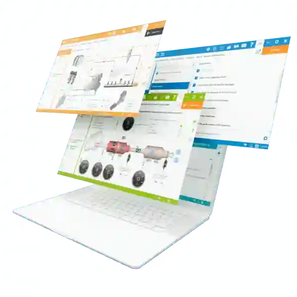
With Jaltest INFO Web, the user gains access to:
- Possible root causes of the fault
- An interactive wiring diagram of the system
- Step-by-step procedures to test power supply, ground, and communication lines
🔍 Main Hypothesis: Failure in the CAN Line Connecting the NOx Sensor to the ECU
🧪 Step 3: Electrical Testing of the NOx Sensor
Tests performed using a multimeter:
| Test | Result | Conclusion |
| 12V Power Supply | OK | Sensor is powered |
| Ground | OK | Ground circuit is intact |
| Resistance between CAN High and CAN Low | 56 ohms ❌ | Fault detected (Expected: 120 ohms) |
➡️ A lower-than-expected resistance usually indicates a break or short circuit on the CAN Bus.
🛠️ Step 4: CAN Network Analysis with Jaltest
Running the integrated CAN communication test in Jaltest.
Result:
- No signal from the NOx sensor
- Synchronization issue on the CAN Bus
This confirms a communication breakdown, most likely due to a physical wiring fault.
🔍 Step 5: Visual Inspection and Continuity Testing
Using the Jaltest wiring diagram, the relevant harness is located.
- Physical inspection → No visible damage
- Line-by-line continuity test → Break found near an intermediate connector under the chassis
🧰 Step 6: Harness Repair
- Clean reconnection of both CAN wires
- Reinforced insulation
- Final resistance reading: 120 ohms ✅
- Communication test: Network operational
- Fault code cleared
- Road test: Vehicle restored, no warning lights, power recovered
✅ Conclusion
This case highlights the importance of combining fault code reading, electrical testing, and technical diagrams to establish a reliable diagnosis.
With Jaltest, even a complex issue like this becomes visible, measurable, and repairable.


