
A sensor is showing an incorrect value. Does it really need to be replaced?
CAN Bus diagnostics is essential for identifying communication problems between electronic control units (ECUs) in vehicles and machines. When several ECUs report faults or equipment stops responding, checking the CAN network can help identify the real cause.
CAN Bus Diagnostics: 7 Essential Measurements
A sensor never works alone. It communicates with a control unit, often referred to as the ECU – Electronic Control Unit.
A typical circuit includes:
- a power supply;
- a ground connection;
- a sensor;
- a signal wire;
- connectors;
- a wiring harness;
- an ECU.
If one of these elements is faulty, the ECU may receive incorrect information and store a fault code.
The correct approach is therefore to check the entire circuit before blaming a single component.
1. Start With the Fault Code
The first step is to read the fault codes stored in the ECUs.
The code helps indicate where to begin the investigation, but it does not always identify the exact cause of the fault.
For example, a pressure sensor fault may come from:
- the sensor;
- a broken wire;
- low supply voltage;
- a poor ground;
- a corroded connector;
- or, less commonly, the ECU.
A fault code is a clue, not a conclusion.
2. Identify the Sensor and Its Circuit
Before measuring anything, you need to understand how the component works.
A wiring diagram helps identify:
- the sensor power supply;
- its ground;
- the signal wire;
- intermediate connectors;
- the ECU it is connected to.
This prevents technicians from testing the wrong wires or wasting time on the wrong section of the harness.
3. Check the Power Supply and Ground
Before replacing the sensor, make sure it receives the correct voltage.
Depending on the system, the sensor may use a reference voltage supplied directly by the ECU.
The ground connection should also be checked.
A poor ground can create an incorrect reading even when the sensor itself is working properly.
4. Check the Signal
Once the power supply has been confirmed, check the signal being sent to the ECU.
Compare the measured value with the technical reference data.
If the sensor sends the correct value but the ECU does not receive it, the wiring between the two components needs to be checked.
5. Inspect the Wiring Harness and Connectors
Electrical faults are not always visible.
Look for:
- broken or crushed wires;
- displaced pins;
- corrosion;
- poorly locked connectors;
- signs of moisture;
- cables damaged by vibration or heat.
For intermittent faults, gently moving the wiring harness during testing may sometimes help reproduce the problem.
Jaltest INFO Web in Action
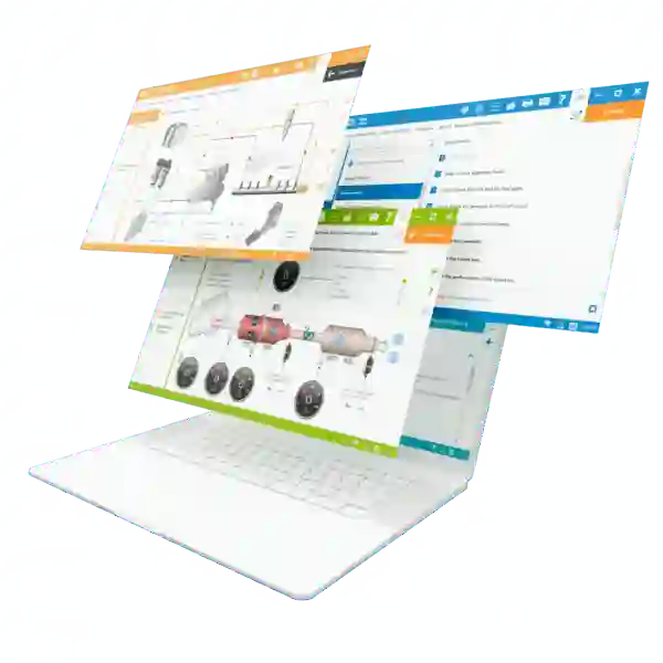
With Jaltest INFO Web, technicians can follow the electrical circuit more accurately.
Depending on the selected vehicle or machine, the platform can provide access to:
- wiring diagrams;
- component locations;
- connectors and pinouts;
- fault code information;
- technical reference values;
- inspection and repair procedures.
Take the example of a sensor showing an inconsistent reading.
The technician can consult the wiring diagram, identify the power, ground and signal wires, locate intermediate connectors and then check the circuit all the way to the ECU.
This helps determine whether the fault really comes from the sensor or from another part of the circuit.
The Method to Remember
For effective electrical fault diagnosis:
Fault code → Diagram → Power supply → Ground → Signal → Wiring → ECU
This simple logic helps reduce guesswork and unnecessary component replacement.
Conclusion
Diagnosing an electrical fault is mainly about following the right method.
A fault stored for a sensor does not automatically mean that the component has failed. Before replacing it, technicians should check the power supply, ground, signal and circuit continuity all the way to the ECU.
With Jaltest INFO Web, technicians have access to the technical information needed to follow the circuit from the sensor to the ECU and confirm the real cause of the fault more quickly.